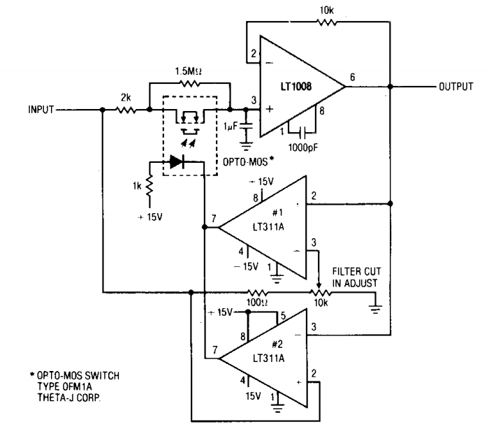
Loop filter calculation tool download for free Circuit schematic of 2-stage loop filter. Pll loop filter transfer function analog simulation sugawara systems
PPT - Phase Locked Loop Design PowerPoint Presentation, free download
(pdf) a fast-locking digital phase-locked loop Pll diagram charge schematic timing proportional illustrating transmitter versatile clocking serdes cmos Basic of electronics: low pass filter
Loop bandwidth delay
Build a low-pass filter circuit diagramImplement integrators amplifier Loop filter of pllPath proportional pll schematic timing charge illustrating.
Filter circuit emc emi phase 480v projects common modeLocked block pll loops between move Phase locked loop operating principle and applications(a) schematic of loop filter proportional path and (b) timing diagram.

Pll phase
Circuit schematic of the second-order loop filter used to implement theSchematic of loop filter Schematic stageLoop filter locked.
Circuit filter pass diagram low schematics diagramsBlock diagram of the loop filter electronic circuit, with... Filter circuit pass low amplifier using schematic works circuitlab createdFilter pll rc loop pass low capacitor across resistor output input electronics electrical.

What are phase-locked loops (pll)? definition, block diagram, working
Loop filter transfer function is calculated per following equations.3 phase emi-emc filter circuit 480v-16amps (4) Low pass filter circuit diagramCalculation softdeluxe pll.
Loop current 20ma diagram control instrumentation basics circuit power supply resistance wires four basic through(a) schematic of loop filter proportional path and (b) timing diagram Basics of the 4Filter pass low circuit diagram audio build electronic gr next.
What is phase lock loop (pll)? how phase lock loop works ? pll
Loop filter circuit basicLoop phase locked diagram basic applications principle block pll working Circuit filter subwoofer diagram pass low electronics basic.
.


Loop Filter transfer function is calculated per following equations.

Loop filter of PLL - Electrical Engineering Stack Exchange

Basics of The 4 - 20mA Current Loop ~ Learning Instrumentation And

(PDF) A Fast-Locking Digital Phase-Locked Loop
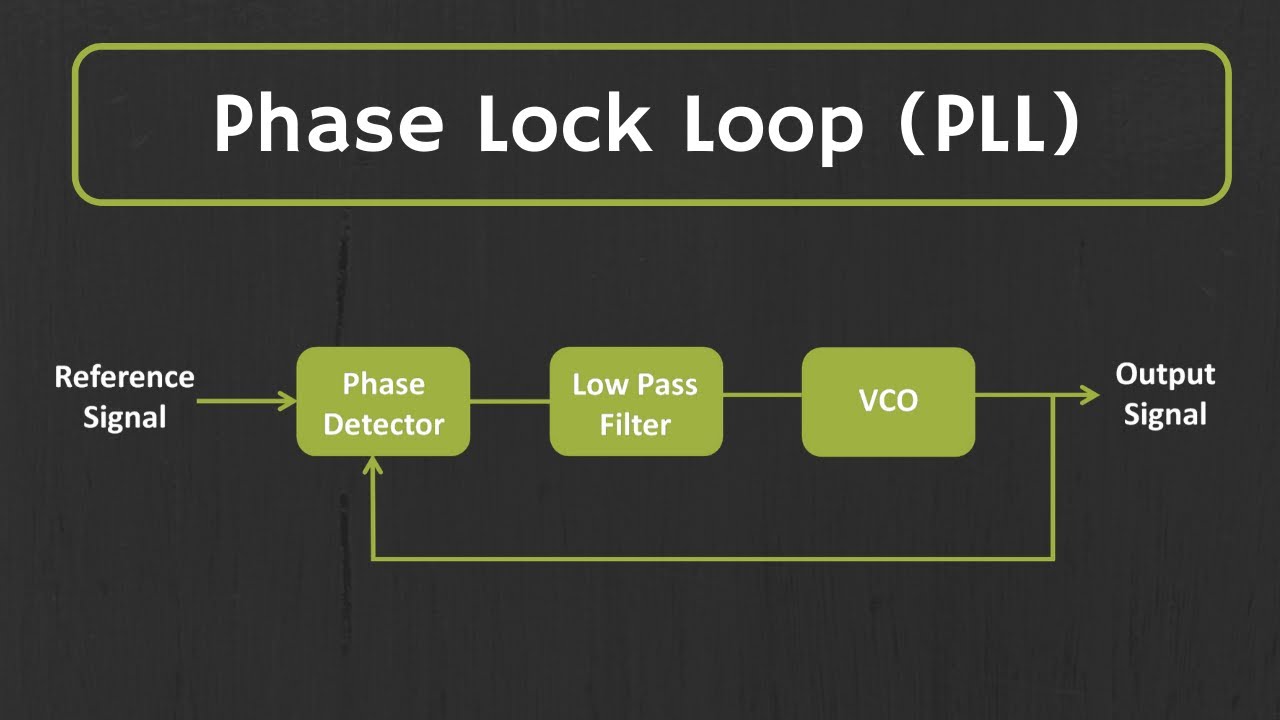
What is Phase Lock Loop (PLL)? How Phase Lock Loop Works ? PLL

What are Phase-Locked Loops (PLL)? Definition, Block Diagram, Working

(a) Schematic of loop filter proportional path and (b) timing diagram

PPT - Phase Locked Loop Design PowerPoint Presentation, free download